Illustrations#
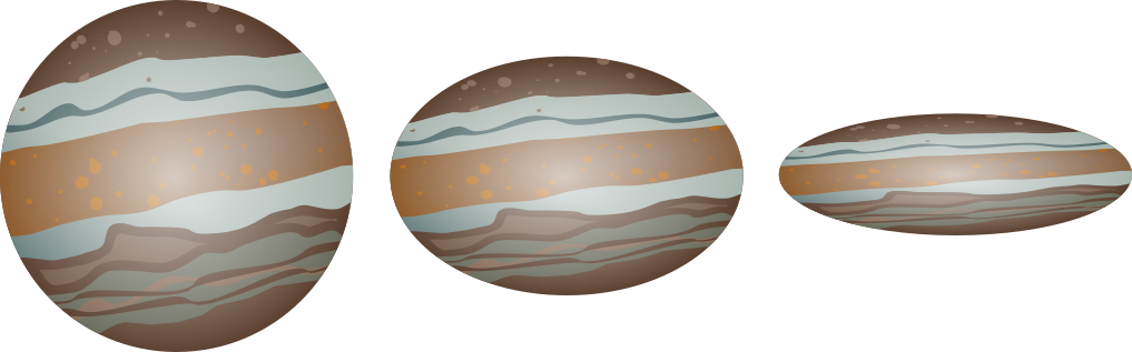
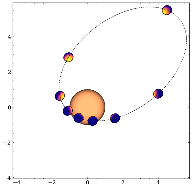
squishyplanet includes an illustration tool to help visualize the implications of different parameter choices. Below are a few examples of its output. See OblateSystem.illustrate for more, and be sure to check out Geometry Visualizations for an
overview of the parameters we’ll fiddle with here.
[1]:
import jax

jax.config.update("jax_enable_x64", True)
import jax.numpy as jnp
import matplotlib.pyplot as plt

from squishyplanet import OblateSystem
[2]:
state = {
    "t_peri": 0.0,
    "times": jnp.linspace(0.0, 5, 400),
    "a": 5.0,
    "e": 0.8,
    "omega": jnp.pi / 3,
    "f1": 0.3,
    "f2": 0.1,
    "obliq": -jnp.pi / 2,
    "prec": jnp.pi / 4,
    "period": 10,
    "r": 0.3,
    "i": jnp.pi / 4,
    "ld_u_coeffs": jnp.array([0.2, 0.65]),
    "tidally_locked": False,
}

system = OblateSystem(**state)

system.illustrate(
    true_anomalies=jnp.arange(0, 2 * jnp.pi, jnp.pi / 4),
    window_size=10.0,
    reflected=True,
)
Reflected Light#
[4]:
base = {
    "t_peri": 0.0,
    "times": jnp.linspace(0.0, 5, 400),
    "a": 2.0,
    "period": 10,
    "r": 0.3,
    "i": 0.0,
    "ld_u_coeffs": jnp.array([0.2, 0.65]),
}

state = {
    "f2": 0.5,
    "obliq": -jnp.pi / 2,
    "tidally_locked": True,
}

state = {**base, **state}
system = OblateSystem(**state)

system.illustrate(
    true_anomalies=jnp.linspace(0, 2 * jnp.pi, 9),
    window_size=5.0,
    reflected=True,
)
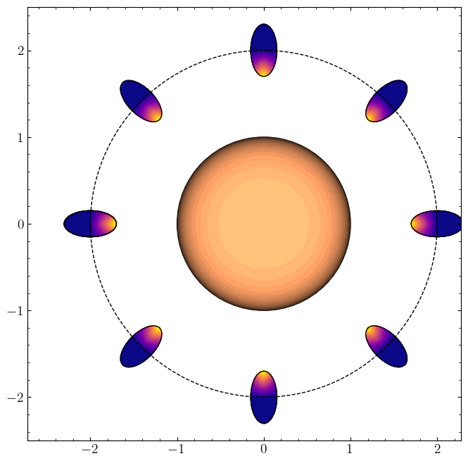
squishyplanet is only capable of modeling Lambertian reflections from planets with uniform albedos, but users can set/fit for that albedo.
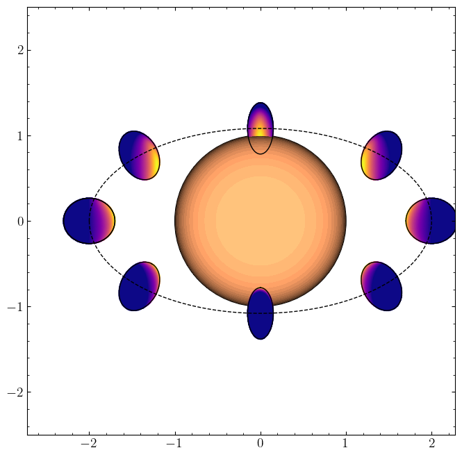
Here’s what the system looks like as we increase the inclination. Note that the projected area of a tidally locked planet changes over the course of the orbit, which imprints itself on the phase curves and transits.
[5]:
state = {
    "f2": 0.5,
    "obliq": -jnp.pi / 2,
    "tidally_locked": True,
}

state = {**base, **state}
state["i"] = 1.0
system = OblateSystem(**state)

system.illustrate(
    true_anomalies=jnp.linspace(0, 2 * jnp.pi, 9),
    window_size=5.0,
    reflected=True,
)
Limb darkening profile check#
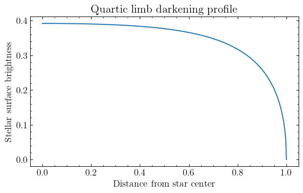
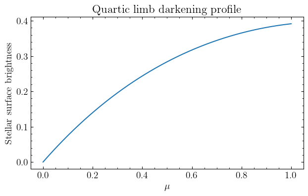
OblateSystem does not have many methods accessible to the user. Aside from lightcurve, loglike, and illustrate, the remaining two are convenience methods to deal with limb darkening. One of these is limb_darkening_profile, which is included to help visualize the limb darkening profile:
[6]:
stellar_radii = jnp.linspace(0, 1, 500)
ld_profile = OblateSystem.limb_darkening_profile(
    ld_u_coeffs=jnp.array([0.2, 0.65, 0.05, 0.1]), r=stellar_radii
)

fig, ax = plt.subplots()
ax.plot(stellar_radii, ld_profile)
ax.set(
    xlabel="Distance from star center",
    ylabel="Stellar surface brightness",
    title="Quartic limb darkening profile",
)

stellar_mu = jnp.linspace(0, 1, 500)
ld_profile = OblateSystem.limb_darkening_profile(
    ld_u_coeffs=jnp.array([0.2, 0.65, 0.05, 0.1]), mu=stellar_mu
)

fig, ax = plt.subplots()
ax.plot(stellar_radii, ld_profile)
ax.set(
    xlabel=r"$\mu$",
    ylabel="Stellar surface brightness",
    title="Quartic limb darkening profile",
);
Angle conventions#
squishyplanet follows the standard orbit orientation angles/conventions:
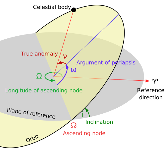
This diagram, and a good explanation for all the angles pictured, is from the wikipedia page for orbital elements. We recommend bookmarking this page: chances are you’ll be returning to it often if you think about orbits and modeling.
After an orbit is defined by its Keplerian elements, we orient it on the sky according to the rotations given in Murray and Correia 2010. The observer is placed at [0,0,+\(\infty\)], and to transform from the planet’s frame (subscript \(p\)) to the sky frame (subscript \(s\)), we apply the following rotations:
Where \(P_x(*)\) is the rotation matrix about the x-axis and \(P_z(*)\) is the rotation matrix about the z-axis. The angles \(\Omega\), \(i\), and \(\omega\) are the longitude of the ascending node, inclination, and argument of periastron, respectively.
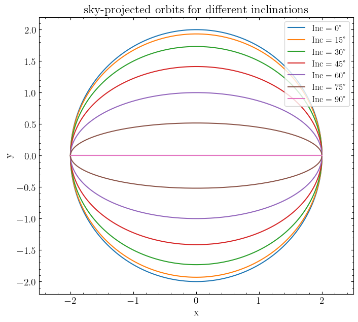
After this transformation, an inclination of \(i=90^\circ\) gives us a transiting orbit, while \(i=0^\circ\) gives us a face-on orbit:
[7]:
# Inclination

base = {
    "t_peri": 0.0,
    "times": jnp.linspace(0.0, 5, 400),
    "a": 2.0,
    "period": 5,
    "r": 0.3,
    "i": 0.0,
    "ld_u_coeffs": jnp.array([0.0, 0.0]),
    "tidally_locked": False,
}
planet = OblateSystem(**base)

fig, ax = plt.subplots(figsize=(8, 8))
for inc in jnp.arange(0, 91, 15):
    base["i"] = jnp.deg2rad(inc)
    planet = OblateSystem(**base)
    x = planet.state["x_c"]
    y = planet.state["y_c"]

    ax.plot(x, y, label=f"Inc = {inc}°")
ax.set(
    xlabel="x",
    ylabel="y",
    title="sky-projected orbits for different inclinations",
    xlim=(-2.5, 2.5),
    aspect="equal",
)
ax.legend(prop={"size": 12});
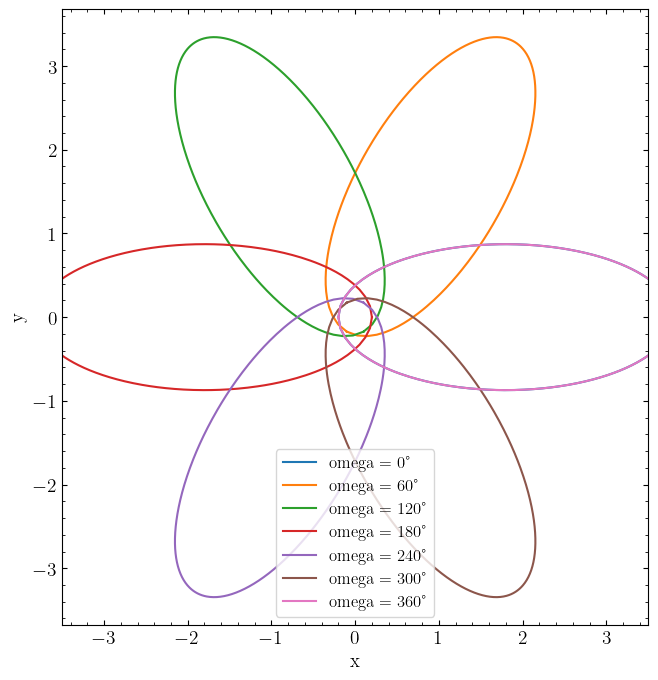
We can also illustrate the effect of changing \(\omega\) when you have an eccentric orbit:
[8]:
# little omega

# little omega is a rotation about the pole of the orbital plane. When inclination=0,
# the orbital planet *is* the sky plane, so little omega is just a rotation about Z

base = {
    "t_peri": 0.0,
    "times": jnp.linspace(0.0, 5, 400),
    "a": 2.0,
    "e": 0.9,
    "omega": 0.0,
    "period": 5,
    "r": 0.3,
    "i": 0.0,
    "ld_u_coeffs": jnp.array([0.0, 0.0]),
    "tidally_locked": False,
}
planet = OblateSystem(**base)

fig, ax = plt.subplots(figsize=(8, 8))
for omega in jnp.arange(0, 361, 60):
    base["omega"] = jnp.deg2rad(omega)
    planet = OblateSystem(**base)

    ax.plot(planet.state["x_c"], planet.state["y_c"], label=f"omega = {omega}°")

ax.set(xlabel="x", ylabel="y", xlim=(-3.5, 3.5), aspect="equal")

ax.legend(prop={"size": 12});
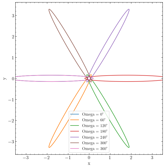
And finally, the effect of changing \(\Omega\), which transits and RVs are insensitive to:
[9]:
# big Omega- transits and RVs are not sensitive to this parameter,
# so by default we always set it to Pi. This ensures that a transiting planet moves
# left->right and reaches conjunction at true anomaly=pi/4 (if it's circular)

# still, it can be set to other values in squishyplanet
# here, we give each orbit some inclination but keep little omage fixed at 0, emphazing
# that big Omega is a rotation around the sky Z axis

base = {
    "t_peri": 0.0,
    "times": jnp.linspace(0.0, 5, 400),
    "a": 2.0,
    "e": 0.9,
    "omega": 0.0,
    "Omega": 0.0,
    "period": 5,
    "r": 0.3,
    "i": 80 * jnp.pi / 180,
    "ld_u_coeffs": jnp.array([0.0, 0.0]),
    "tidally_locked": False,
}
planet = OblateSystem(**base)

fig, ax = plt.subplots(figsize=(8, 8))
for Omega in jnp.arange(0, 361, 60):
    base["Omega"] = jnp.deg2rad(Omega)
    planet = OblateSystem(**base)

    ax.plot(planet.state["x_c"], planet.state["y_c"], label=f"Omega = {Omega}°")

ax.set(xlabel="x", ylabel="y", xlim=(-3.5, 3.5), aspect="equal")

ax.legend(prop={"size": 12});
[ ]: